

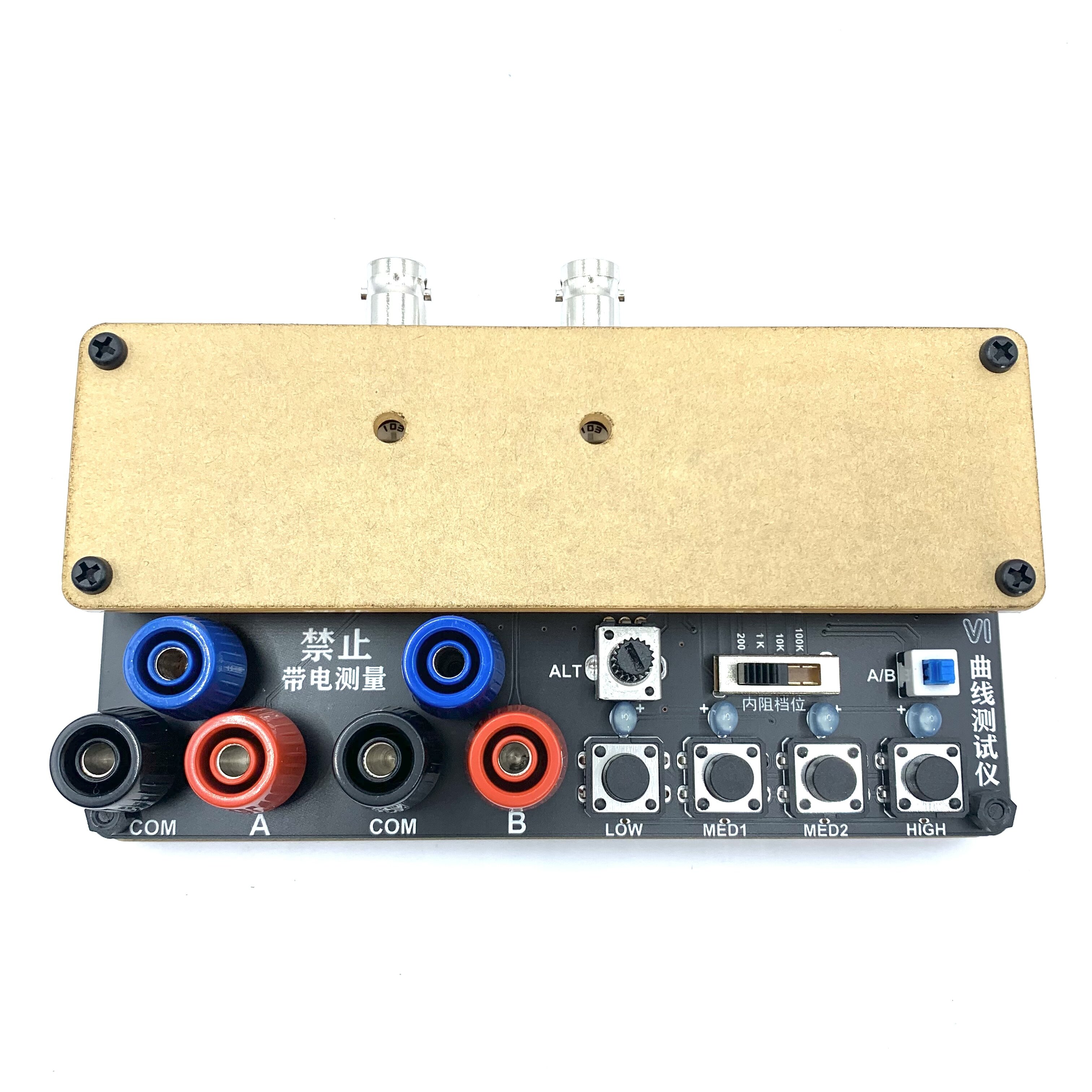


Dual-channel VI Curve Tester, Displaying 2 Waveforms at the Same Time for Easy Comparison
77

 Direct purchase from the factory
Zabezpečená platba

 Dárek zdarma
 Dopravní podmínky
 Reklamační podmínky
Dárek Zdarma
Vítejte v Roymall, vaší profesionální obchodní stránce pro prémiové dárky. Velmi si vážíme vaší podpory a jako poděkování nabízíme dárek zdarma s každým nákupem. Připraveni prozkoumat naši sbírku? Prohlédněte si náš výběr, uskutečněte objednávku a těšte se na dárek zdarma s vaším nákupem.Dopravní Podmínky
Objednávky zpracováváme do 2 dnů. Objednávky vložené o víkendu nebo svátcích budou zpracovány následující pracovní den.Standardní doba dodání je 5-7 pracovních dnů.Doba dodání se může lišit v závislosti na destinaci.1. Reklamační Podmínky
Přijímáme pouze vrácení zboží zakoupeného přímo z roymall.com. Dárky zdarma nelze vrátit. Vrácené zboží musí být nepoužité a v původním obalu.Vrácení zpracujeme do 3-5 pracovních dnů po obdržení.Personalizované předměty nelze vrátit.Kontaktujte nás: service@roymall.com nebo Whatsapp: +86193598494712.Podmínky Vrácení Peněz
Obdržíte plnou náhradu po obdržení a kontrole vráceného zboží. Náklady na dopravu nejsou vratné.Kontaktujte nás: service@roymall.com nebo Whatsapp: +8619359849471Two-way VI curve tester, which can display two-way waveforms at the same time, which is convenient for comparison.
4 levels of internal resistance adjustable, 4 test frequencies, can be used when connected to an oscilloscope, both analog oscilloscopes and digital oscilloscopes can be used
Oscilloscope parameter settinguff1a
*. Adjust the oscilloscope to X-Y mode(different oscilloscopes have different adjustment methods, please explore by yourself)
* Adjust the vertical parameters of the 2 channels of X Y to 1V/div, and only one of the single-track oscilloscopes needs to be adjusted. ,
*The analog oscilloscope does not need to adjust the time base, the digital oscilloscope time base is adjusted between 1-5ms
*After the connection is correct, the oscilloscope will display a horizontal line. If a vertical line is displayed, the xY plug will be reversed.
*Adjust the vertical and horizontal parameters, the horizontal and vertical lines are in the display box.
Method of connecting analog oscilloscopeuff1a
The analog oscilloscope connection is relatively simple, and different oscilloscopes are slightly different.
Adjust the oscilloscope to xY mode. Some oscilloscopes can be selected by pressing the buttons, while others are selected by the knob to xY mode. Please study by yourself.
Connect the BNC cable to the oscilloscope and power on. Normally, a horizontal line will be displayed. Adjust the xY vertical channel parameters, about 1V/div, and then adjust the x Y attenuation so that the horizontal line is in the display frame. It can also pass the VI test version. The x attenuation potentiometer on the upper side can assist in adjusting the length of the horizontal line. If the test pen iis short-circuited, a vertical line will be displayed under normal circumstances. If the vertical line is too long or too short, you need to adjust the Y channel parameters to make the vertical line in the display frame. Half grid or 1 grid to the edge is better. If the horizontal and vertical lines are normal, you can enter the normal measurement.
How to connect a digital oscilloscopeuff1a
For digital oscilloscopes, enter the xY mode through the menu or keys. The two channels of xY are adjusted to 1V/div,and the single-track oscilloscope only needs to adjust the Y channel. Adjust the time base to 1-5 milliseconds. The xY channel selects DC coupling, and the
attenuation is 1x.
When the oscilloscope is not connected, the screen should be a bright spot. Adjust the horizontal and vertical to center the bright spot. Connect the VI tester. Normally, it should be a horizontal line. Adjust the 103 potentiometer at the top of the VI board to make the horizontal line in the display frame. , Half a grid or 1 grid to the edge is
better. Short-circuit the test leads, and the display should be a vertical line at this time. Adjust the Y channel parameters so that the vertical line is in the display frame. So far, debugging is basically over.
When testing the circuit board online, do not charge the circuit board. If there is a large capacitor on the circuit board, discharge the capacitor first, otherwise it is easy to burn out the VI test board.

![[Limited big discount] DG852 Pro Series Function Arbitrary Waveform Generator 50MHz 2CH 625MSa/s High Accuracy Portable Design with 7 inch Touch Screen Low Jitter Rich Modulation for Communication Motor Control](https://static.roymall.com/d/file/mall/titlepic/233/xfhkrh2lnce.jpg?x-oss-process=image/resize,w_237/quality,Q_80/format,webp)


